- What is a pre stressed I girder? Why should a designer choose I girders when we are having double deck bridges and substantiate your answer with structural clearances?
Ans:-
A pre stressed I girder is a type of structural member commonly used in bridge construction. It consists of steel or concrete beam in the shape of an "I" that is pre stressed, meaning it is subjected to an initial compressive force during fabrication to counter act the tensile stresses that will be induced when the girder is in service.
The choice of I girders for double deck bridges can be substantiated by several factors, including structural clearances. Here are some reasons why designers might opt for I girders in such situations:
- Vertical Space Optimization: Double deck bridges aim to maximize the efficient use of vertical space by accommodating two levels of traffic. I girders, with their tall and slender profile, provide a favourable strength-to-weight ratio. This allows for the creation of a compact bridge cross-section, minimizing the overall height of the bridge and optimizing the vertical clearance between the decks.
- Long-Span Capability: I girders are known for their ability to span long distances without the need for intermediate supports. This characteristic is particularly advantageous in double deck bridges, where maintaining clear space below for vehicular or pedestrian traffic is essential. By employing I girders, designers can achieve longer spans between piers, reducing the number of supports required and enhancing the clearance beneath the bridge.
- Structural Stability: I girders possess inherent stability due to their shape, with the top and bottom flanges connected by a web. This configuration provides resistance against lateral forces and helps maintain the structural integrity of the bridge. In the case of double deck bridges, where higher loads and additional dynamic effects may be present, the stability of I girders contributes to the overall safety and durability of the structure.
- Construction Efficiency: I girders can be prefabricated off-site, allowing for efficient construction and reduced on-site disruption. The use of precast or pre stressed I girders enables faster assembly and installation compared to other bridge construction methods. This advantage is especially beneficial when building double deck bridges, as minimizing construction time helps mitigate traffic disruptions on both upper and lower decks.
In summary, designers choose I girders for double deck bridges due to their vertical space optimization, long-span capability, structural stability, and construction efficiency. These advantages, along with careful consideration of structural clearances, contribute to the successful design and implementation of double deck bridge projects.
2. Explain the load flow behaviour in a pre stressed I girder for a metro viaduct?
Ans:-
In a pre stressed I girder used for a metro viaduct, the load flow behaviour is influenced by several factors, including the applied loads, the pre stressing forces, and the structural properties of the girder. Here is an explanation of the load flow behaviour in such a girder:
- Dead Load: The dead load refers to the weight of the girder itself, as well as any permanent components attached to it, such as the track, ballast, and utilities. Dead load creates a constant downward force on the girder, resulting in compressive stresses in the concrete and tensile stresses in the bottom flange.
- Live Load: Live load represents the dynamic loads exerted by the moving metro trains and their occupants. As the train travels along the viaduct, it imparts a series of concentrated loads on the girder. These loads create additional bending moments and shear forces within the girder, causing variations in the internal stresses.
- Pre stressing Forces: Pre stressing is a technique used to introduce compressive stresses into the girder before it is subjected to service loads. The pre stressing forces are typically applied through pre-tensioning or post-tensioning methods. These forces counteract the tensile stresses induced by the applied loads, enhancing the overall load-carrying capacity of the girder and reducing deflections.
- Flexural Behaviour: The I girder's primary load-carrying mechanism is its flexural behaviour. The applied loads, including dead load and live load, create bending moments in the girder. The top flange is subjected to compressive stresses, while the bottom flange experiences tensile stresses. The web of the girder resists the shear forces generated by the bending moments.
- Shear Behaviour: In addition to bending moments, the load flow behaviour also involves shear forces. The web of the I girder is designed to resist these shear forces. The pre stressing forces can affect the shear behaviour by modifying the distribution of shear forces along the length of the girder.
- Deflection and Camber: Under load, a pre stressed I girder may experience deflections. The amount of deflection depends on factors such as the magnitude and distribution of the applied loads, the span length, and the stiffness of the girder. To minimize the effects of deflection and achieve the desired profile, a predetermined upward camber is often incorporated into the girder during fabrication.
Overall, the load flow behaviour in a pre stressed I girder for a metro viaduct involves the transfer of loads through bending moments, shear forces, and pre stressing forces. By considering these factors during the design and construction stages, engineers can ensure that the girder adequately supports the applied loads while maintaining the required serviceability and safety requirements for metro viaducts.
- Explain codal provisions required for the design of I girders. Brief about the allowable stress with respect to the IRS CBC code.
Ans:-
The design of I girders, like any other structural elements, is governed by relevant codal provisions and design standards. In the case of I girders in India, the design is guided by the Indian Railways Standard Code of Practice for the Design of Steel or Concrete Bridges (IRC: 112) and the Indian Road Congress (IRC) codes, particularly the Indian Road Congress Bridge Code (IRC: 6) and the Indian Road Congress Code of Practice for Pre stressed Concrete (IRC: 18).
One of the key aspects of design codes is the determination of allowable stresses, which are limits on the maximum stress that a material or structural element can withstand. The allowable stress design method is commonly followed in the Indian context, including the Indian Railways Standard Code (IRC: 112).
The allowable stress for I girders in the Indian Railways Standard Code (IRC: 112) is specified with respect to the Indian Railways Standard (IRS) specifications for concrete and steel. For pre stressed concrete I girders, the allowable stresses are determined based on the permissible stresses in concrete and steel under different loading conditions.
In the Indian context, the allowable stresses for concrete and steel in pre stressed I girders are generally determined by the following considerations:
- Permissible Stresses in Concrete: The permissible compressive and tensile stresses in concrete are determined based on factors such as the grade of concrete, age of pre stressing, and the degree of pre stress. The permissible stresses for concrete are specified in the Indian Road Congress Code of Practice for Pre stressed Concrete (IRC: 18).
- Permissible Stresses in Steel: The permissible stresses in the steel reinforcement of the I girder are determined based on the grade of steel and the type of loading. The Indian Railways Standard Code (IRC: 112) provides specifications for allowable stresses in steel reinforcement under different loading conditions.
It is important to note that the exact values of allowable stresses for I girders can vary depending on the specific design requirements, bridge span, loading conditions, and other factors. Designers and engineers must refer to the most up-to-date versions of the relevant codes and standards, as they are periodically revised and updated.
In summary, the codal provisions required for the design of I girders in India include the Indian Railways Standard Code (IRC: 112) and the Indian Road Congress codes (IRC: 6 and IRC: 18). The allowable stress design method is typically followed, and the allowable stresses for concrete and steel are determined based on the grade of materials and loading conditions specified in the respective codes and specifications.
- As per IRS CBC Table 11, SLS allowable stresses for RCC structure is 0.5 fck whereas for a PSC structure it is 0.4 fck. Explain the technical details of the aforesaid values. Also explain the behaviour of stresses in a PSC girder with respect to the fck values
Ans:-
In the Indian context, the Indian Railways Standard Code (IRC) governs the design and construction of railway bridges. Table 11 of the Indian Railways Standard Code (IRC CBC) provides the allowable stresses for serviceability limit state (SLS) for reinforced concrete (RCC) and pre stressed concrete (PSC) structures.
According to Table 11 of IRC CBC, the allowable stresses for RCC structures are taken as 0.5 times the characteristic strength of concrete (fck), while for PSC structures, it is taken as 0.4 times fck. Here are the technical details behind these values:
- RCC Structures: Reinforced concrete structures, such as RCC girders, rely on the combined strength of concrete and steel reinforcement. The allowable stresses for RCC structures are determined by considering the behaviour of both materials.
- Concrete Strength (fck): The characteristic strength of concrete (fck) is a measure of its compressive strength. It represents the strength below which only a small proportion of test results are expected to fall. The value of fck is specified in the design code based on the desired level of safety and structural performance.
- Allowable Stress for RCC: The allowable stress for concrete in RCC structures is taken as 0.5 times fck. This factor of 0.5 provides a safety margin by reducing the actual stress level to ensure the structure remains within its serviceability limits and meets the required performance criteria.
- PSC Structures: Pre stressed concrete structures, such as PSC girders, incorporate pre stressing forces to counteract the tensile stresses induced by applied loads. The allowable stresses for PSC structures are determined considering the behavior of pre stressed concrete.
- Concrete Strength (fck): The characteristic strength of concrete (fck) remains the same for both RCC and PSC structures.
- Allowable Stress for PSC: The allowable stress for concrete in PSC structures is taken as 0.4 times fck. This reduced value is due to the fact that prestressing introduces compressive stresses in the concrete, which reduces the tensile stresses that would otherwise be present. Therefore, the allowable stress in the concrete is reduced to account for the effect of prestressing and to ensure the structural behavior remains within acceptable limits.
Behavior of Stresses in PSC Girder with respect to fck values: In a PSC girder, the prestressing forces applied during fabrication induce compressive stresses in the concrete before the girder is subjected to service loads. This prestressing reduces the tensile stresses that would be present without prestressing, enhancing the overall load-carrying capacity and performance of the girder.
The fck value is utilized in the design of PSC girders to determine the characteristic strength of concrete. It serves as a reference value for various design calculations. The allowable stress for concrete in PSC structures is taken as 0.4 times fck, ensuring that the design remains within the desired safety and serviceability criteria.
By using prestressed concrete, PSC girders exhibit improved resistance to cracking, increased stiffness, and enhanced load-carrying capacity compared to RCC girders. The reduced allowable stress in PSC concrete reflects the specific behavior of prestressed concrete and ensures the structural integrity and performance of PSC girders under service loads.
- As IRS CBC, Table 10, what is design crack width and what are various exposure condition? Identify your city from the code and mention its exposure condition in India.
However, in general concrete design, crack width control is an important aspect to ensure the durability and serviceability of structures. Design crack width refers to the maximum allowable width of cracks that can occur in concrete elements under specified conditions. Limiting crack width helps prevent the ingress of harmful substances, such as water and aggressive chemicals, into the concrete, which can lead to corrosion of reinforcement and other deterioration issues.
Exposure conditions refer to the environment to which a concrete structure is exposed, including the presence of aggressive agents or external conditions that can affect its durability. Exposure conditions are typically categorized based on factors such as humidity, temperature, chemical exposure, and severity of exposure.
In the Indian context, the exposure conditions for concrete structures are often classified according to the guidelines provided by the Bureau of Indian Standards (BIS) in the Indian Standard Code for Concrete (IS 456:2000). The classification of exposure conditions in IS 456:2000 includes the following categories:
- Mild Exposure (M): This includes indoor environments or outdoor environments with low humidity and absence of any aggressive substances.
- Moderate Exposure (S): This category encompasses outdoor environments with moderate humidity and a moderate level of exposure to moisture and atmospheric pollution.
- Severe Exposure (C): This refers to outdoor environments with high humidity, moisture, and exposure to aggressive substances such as chlorides, sulfates, and carbon dioxide.
- Very Severe Exposure (XC): This category includes environments with very high humidity and exposure to aggressive substances, such as coastal areas with saltwater spray or structures exposed to chemical fumes.
- Extreme Exposure (XD): This category includes environments with extreme exposure to aggressive substances, such as industrial areas with high concentrations of chemicals.
- What is a crossover in railways? Explain about the preference of I girder over U girders on viaduct, where crossovers are being constructed.
Ans:-
In railways, a crossover refers to a track arrangement that allows trains to move from one track to another, usually from one line to a parallel or intersecting line. Crossovers are essential for managing train movements, enabling trains to switch between tracks for various purposes such as overtaking, changing routes, or accessing different platforms.
When constructing viaducts that incorporate crossovers, the preference for I girders over U girders can be attributed to several factors:
- Structural Clearances: Crossovers require additional clearances to accommodate the movement of trains between tracks. I girders, with their tall and slender profile, provide a more favorable clearance profile compared to U girders. The use of I girders allows for sufficient vertical space for the trains to pass beneath the viaduct, ensuring proper clearances between the tracks and minimizing the risk of collisions or obstructions.
- Flexibility and Ease of Construction: I girders offer greater flexibility in design and construction compared to U girders. The open web configuration of I girders allows for the passage of utilities, such as signaling cables or drainage systems, which may be required in the vicinity of crossovers. Additionally, I girders can be prefabricated off-site, leading to faster and more efficient construction, which is advantageous when working in areas with complex track arrangements like crossovers.
- Long-Span Capability: Crossovers on viaducts often involve multiple tracks merging or diverging, which may result in longer spans between piers or supports. I girders are well-suited for long-span applications, as they offer superior load-carrying capacity and structural stability. Their inherent stiffness and strength enable the construction of viaducts with fewer intermediate supports, facilitating the smooth movement of trains through the crossovers.
- Constructability and Maintenance: I girders can be fabricated using different materials such as steel or concrete, allowing for a choice that suits the specific project requirements. Depending on the material used, I girders can offer advantages in terms of durability, maintenance requirements, and resistance to corrosion or environmental factors. These factors contribute to the overall longevity and cost-effectiveness of the viaducts with crossovers.
In summary, the preference for I girders over U girders in viaducts with crossovers is driven by considerations such as structural clearances, flexibility in design and construction, long-span capability, and constructability. By choosing I girders, engineers can ensure sufficient vertical clearances, accommodate utilities, facilitate efficient construction, and provide robust support for the complex track arrangements associated with crossovers.
- What are SIDL considered for a viaduct design?
Ans:-
SIDL, or Superimposed Dead Load, refers to the additional dead loads that are considered in the design of a viaduct or any other structure. These loads are in addition to the permanent or self-weight of the structure itself. SIDL represents the non-permanent loads that may be applied to the viaduct during its service life. The specific SIDL considerations for a viaduct design depend on the anticipated usage and the surrounding environment. Here are some common examples of SIDL considered for viaduct design:
Rail Load
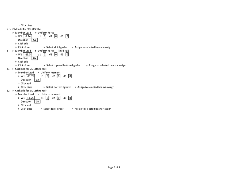
Plinth Load
Third Rail
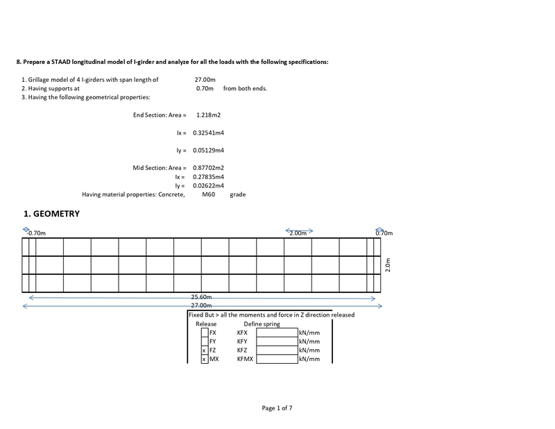
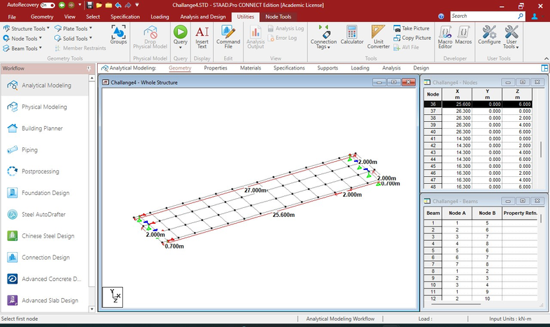
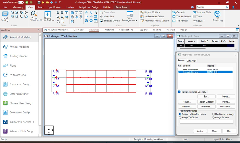
Geometry
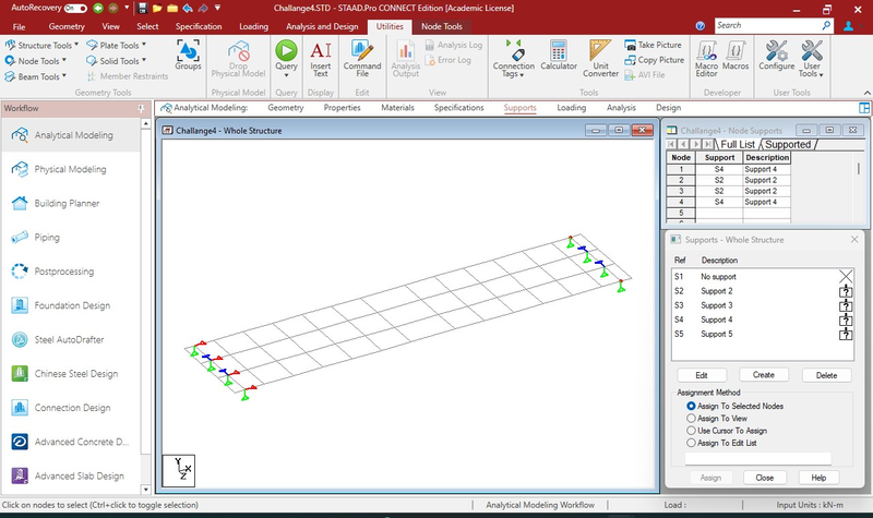
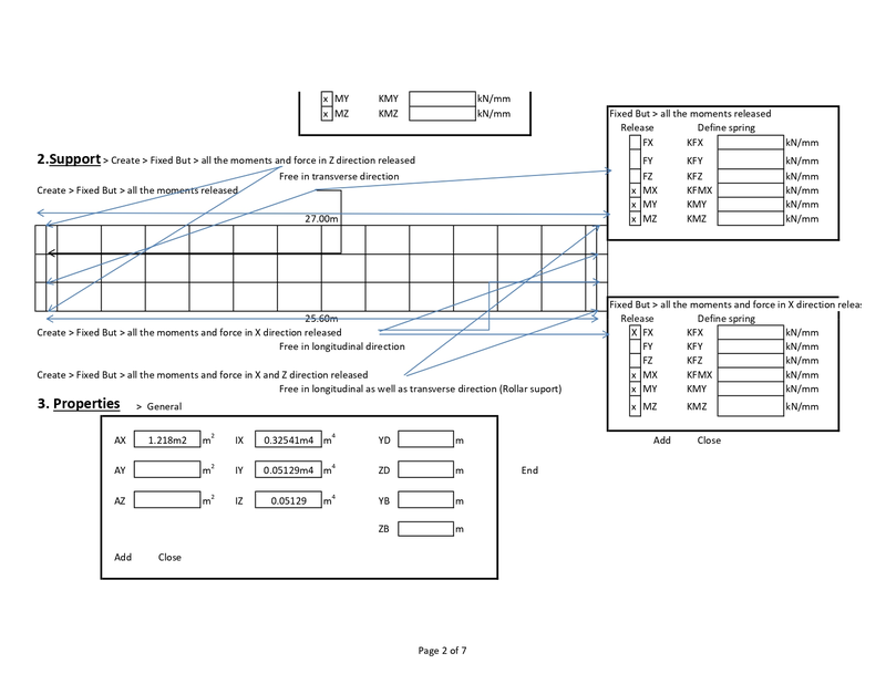
Support
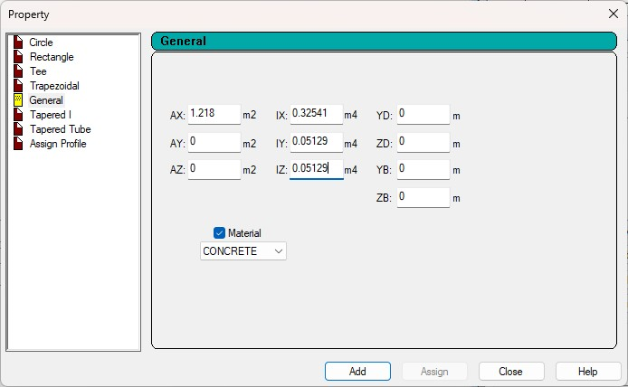
Properties
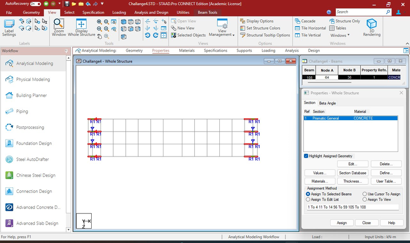
Properties assigned to end beams
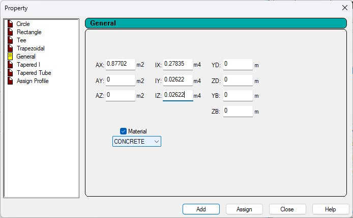
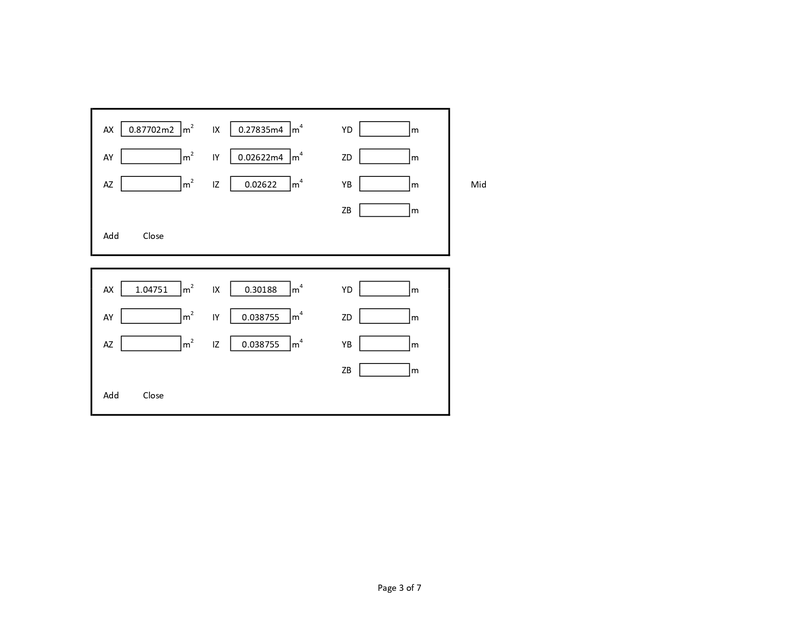
Properties for mid portion of beam
Properties assigned to mid portion of beam
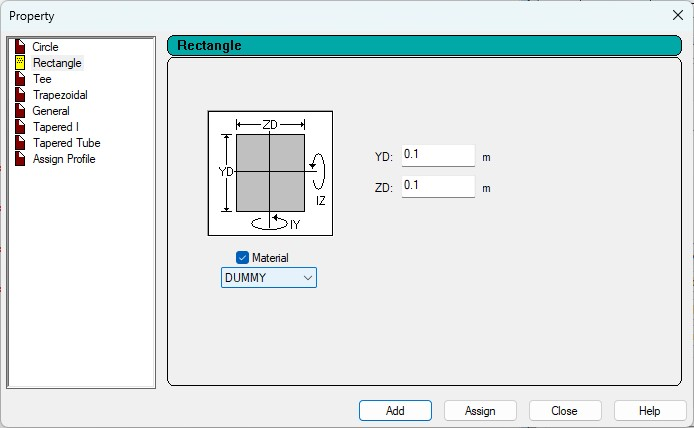
Properties for transverse beam
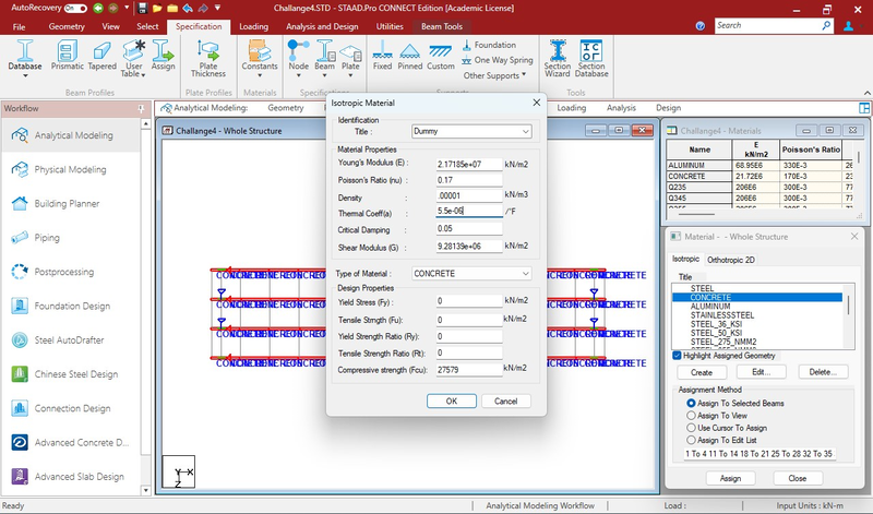
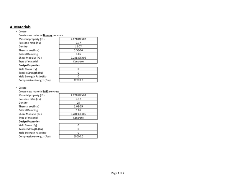
Material Dummy Created
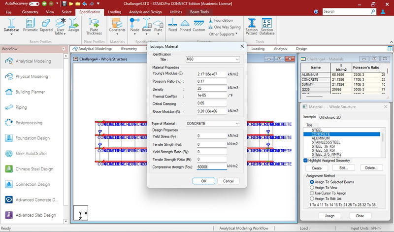
Material M60 created
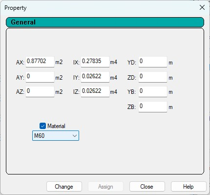
Material M60 assigned
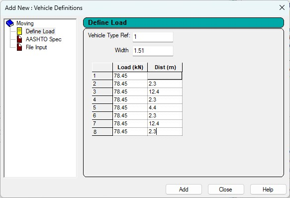
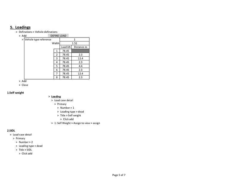
Vehicle defination
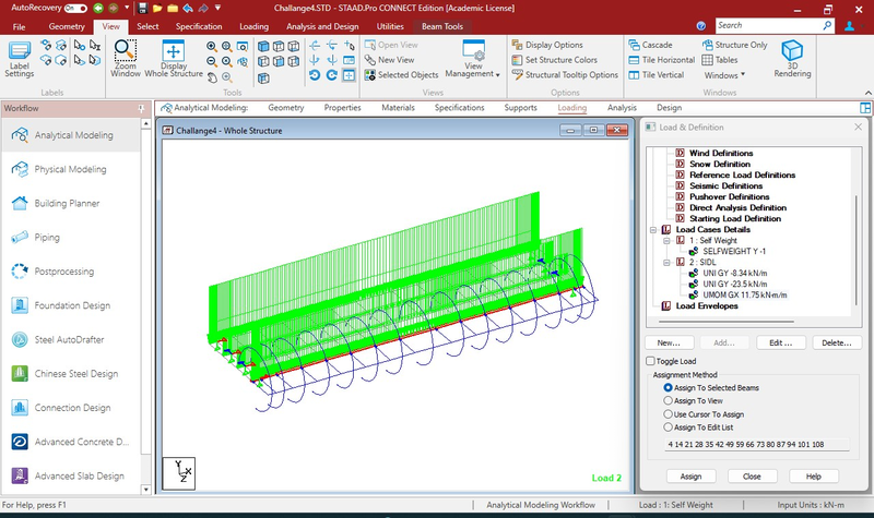
Moment of SIDL
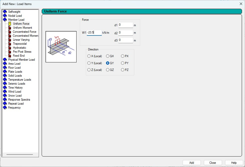
Load of third rail
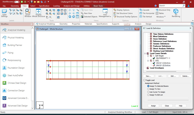
Assigned to end girder
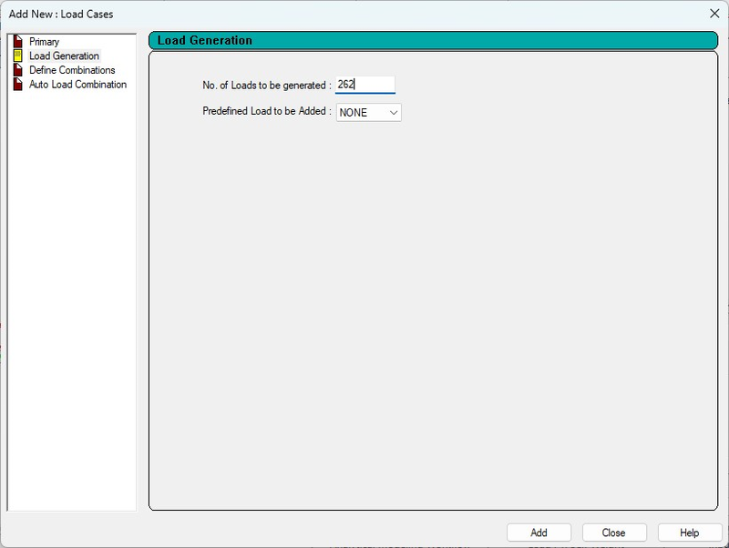
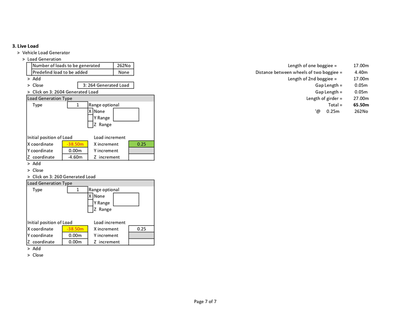
Live Load Generation
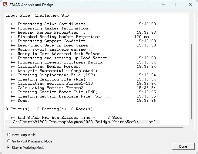
Analysis with Zero error
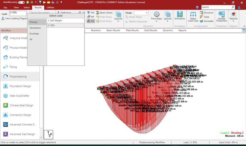
Maximum bending moment for SIDL
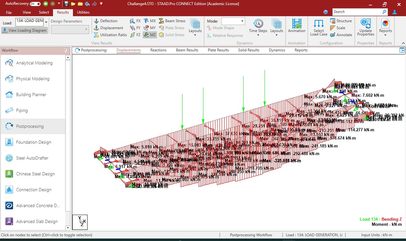
Maximum bending moment generated by vehicle in middle